|
How to: Using Stitch -N- Glue
Pro
Using
Stitch -N- Glue Pro
Stitch-N-Glue Pro allows you to create and customize a stitch and glue kayak with your exact personal specifications and provides you with the ability to produce full sized plans for your design. This section will walk you through the software. 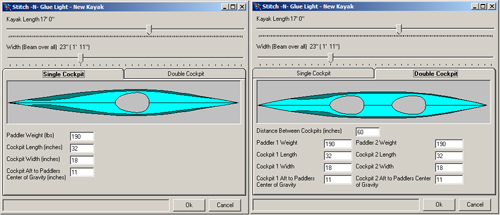
When you open Stitch -N- Glue Pro go to File/New to bring up the New Kayak options. You can specify the kayak length and beam here as well as the required number of cockpits (either one or two). If you already know the details about the paddlers weight and cockpit measurements you can also enter them here. You will not be able to change the number of cockpits later on in the design phase. If you wish to change the number of cockpits, you will have to start a new design. 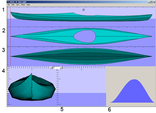
What you see here is the main screen of the program. It consists of six view ports: 1) Side View 2) Top View 3) Bottom View 4) Body Plan 5) Cross Section 6) Volume Distribution In the first three views (side, top, and bottom) you see the curved lines that make up the shape of the kayak. The solid red line shows the current cross section position. You can also see in the Side View where the waterline is in relation to the kayak (this is very useful as it shows where your kayak will sit in the water given whatever load). The lines that make up the shape of the kayak represent the ‘seams’ between the panels of a stitch and glue kayak. When you move one of these lines the panels are automatically adjusted to fit together with the seams in exactly the same position that the lines are in. In order to edit these lines simply click on one of these first three view ports. 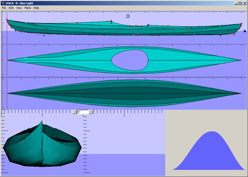
Doing so makes the vertices and tangent handles appear in that view port. This is what you would see if you were to click on the Side View. The curves that make up the lines in the kayak are each defined by vertices and tangent handles. 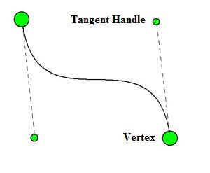
Here is a simpler view of a line segment defined by two vertices (the endpoints) and two tangent handles. Moving either one of the vertices or tangent handles will change the shape of the line. To move one of them in the software, simply click and drag the point on the screen. The line will automatically redraw and the kayak will change shape. You may notice that some vertices and tangent handles cannot be edited this way (such as some of the points that make up the cockpit). We will discuss how to edit these later. The next three view ports, from left to right, are the body plan, current cross section, and volume distribution. 
The Body Plan View: This view allows you to see the entire kayak from the front and back all at once. This view is split into two halves. The left half of the picture represents the view from the bow of the kayak and the right side represents the view from the stern. The number of cross sections or ‘stations’ is set by: Edit/Preferences/Number of Sections. 
The Cross Section View: This shows the currently selected section and where it sits in relation to the waterline. Notice in the Body Plan view port, the currently selected section is drawn with a green line. To scroll through the sections use the left and right buttons centered at the top of these two view ports. The text in between the buttons shows the position (from the bow) of the current section. All length measurements in the program are in inches unless noted otherwise. These two view ports are very useful for visually ensuring that there are only smooth gradual bends in each of the panels. 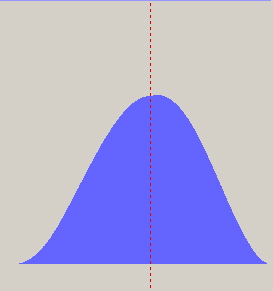
The Volume Distribution View: This view shows the graph of the displaced volume distribution as well as the Longitudinal Center of Buoyancy. This helps the user visualize how the kayak will sit in the water. There is a great deal of data involved in the design of a kayak. This is where the Data window comes in. In the View menu click Data to activate the Data window. 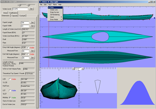
The data window displays all of the kayaks dimensions and hydrostatic calculations. This is also where the user can set the water level as well as kayak and paddler properties.
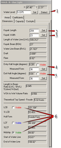
	1) This is where you can adjust the water level, either by
typing it in and pressing the 'Set' button or by clicking 'Detect'.
When you press the 'Detect' button the program will automatically
adjust the water level to make the kayak sit at equilibrium in the
water. When the kayak is at equilibrium, the target displacement is
equal to the design displacement. For information on the
displacements, goto the 'Capacity' tab.

Dimensions tab

	The dimensions tab displays the kayak's size information.

	2) This is where you can adjust the length of the kayak.
The kayak is rescaled in the longitudinal direction to fit the new
length specified in the text box. However, the cockpit(s) will retain
it's (their) proper length dimensions. You can adjust cockpit lenght
on the Cockpits tab. The units here are inches.

	3) This is where you can adjust the beam (width) of the
kayak. Just like when rescaling the length, the cockpits width
will not be affected here. The units here are inches.

	4 & 5) This is where you can make the entry and exit half
angles visible. You can also adjust how far from the start and end
of the water line you wish them to be measured from. In this picture
the entry half angle is measured 36 inches from the start of the
water line. The units here are inches.

	6) The Dimensions tab also has the LCB, LCF and Midship
information. Here you can turn on or off the visibility for each of
these.

	Please refer to Kayak Design Fundamentals, for an
explanation of these  terms (as well as any others).
|
|
|
|
Capacity tab

	The capacity tab displays displacement information.

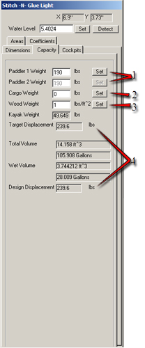
	1) Adjust the paddler(s) weight here. If there is only
one cockpit, 'Paddler 2 Weight' will be dissabled.

	The program will automatically adjust the position of the
cockpit(s) according to the center of gravity and the longitudinal
center of buoyancy. This will ensure that the kayak sits in the
water exactly as it is displayed on the screen.

	2) Enter the expected cargo weight here.

	3) This is where you will predict the weight of the wood
per square foot. The default value is 1 lb/sqare foot. In reality,
this value will most likely be lower than that. 0.7 - 1 lbs/square foot
is the likely range. Ultimately, this value will depend on your materials
and the amount of epoxy used. If you are not sure what value to use, we
recommend talking to other builders on various forums to get an idea.

	4) The total weight of the kayak (paddler(s) + cargo +
kayak weight) is known as the target displacement. The total weight
of the water displaced by the kayak is the design displacement. When
the weight of the water displaced is equal to the total weight of the
kayak, the kayak is in equilibrium. Clicking the 'Detect' button will
determine the correct water level needed to put the kayak at
equilibrium.
|
|
|
|
Cockpit tab
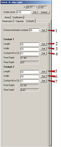
1) Here you can set the distance between cockpits.
Pictured below is how to measure the distance between cockpits.
 2 & 5) To determine the proper length of the cockpit(s),
have the expected paddler sit on the floor with his/her back against the
wall. With both legs out in front, have him/her bend one leg at the knee
90 degrees and measure from the wall to the middle of the shin. This will
provide the minimum length needed for clearance entering and exiting the
kayak. The default length in the program is 32 inches, which should be
fine for most paddlers.
3 & 6) The width of the cockpits will be a value between
the beam of the kayak and the width of the paddlers bottom.
4 & 7) This is simply the distance from the rear of the
cockpit to the paddler's center of gravity. This picture illustrates how
to find a paddler's center of gravity.
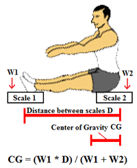 You may want to add a couple inches to the CG to get the Cockpit
Aft to CG in order to make room for the back rest. Just be sure to
account for that extra spacing in the overall cockpit length as well.
|
|
|
|
Areas tab

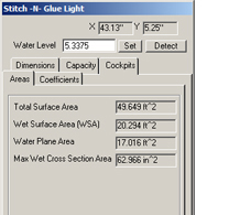
	This tab displays various area measurements of the kayak. The
total surface area of the kayak is used in calculating its weight. The
wet surface area refers to the area of the hull that actually comes in
contact with the water. The water plane area refers to the area of the
2d shape created by the submerged portion of the hull. The max wet
cross section of the kayak is the maximum lateral cross section of the
submerged portion of the hull.

	Please refer to Kayak Design Fundamentals for more detail.
|
|
|
|
Coefficients tab

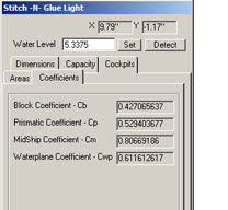
	This tab displays the block, prismatic, midship and waterplane
coefficients for the kayak. Again, please refer to Kayak Design Fundamentals
for more detail.
|
|
|
|
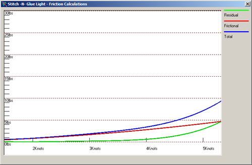
Click View/Drag Curves to view a graph of the kayaks friction calculations for speeds up to the kayaks theoretical hull speed. 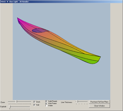
Click View/3D Rendering to view a 3d rendered version of your kayak. Use the mouse to rotate the 3d model around to view from all angles.
|


![]()


